Monday, February 15, 2010

Pumps as Turbines (PaT) Motors as Generators


I have been using Pumps as Turbines and motors as generators very successfully for almost four years now. The optimum (maximum power) speed of a PaT is around 1/2 of its no load speed. So to test,run your PaT and generator with the available head but no electrical load or excitation. Then, for maximum power, you should load the system so it runs at 1/2 this No Load speed. So let's assume you have a six pole electric motor running as a generator at 1200 RPM (nominally). You would be looking for a No Load speed of (approximately) 2400 RPM at the generator shaft. If the PaT is direct coupled the only thing that can be tuned is the impeller diameter assuming the head is fixed. Cut down (on a lathe) the impeller diameter to increase the No Load RPM. If the generator is coupled to the PaT by a V belt the shiv ratios can be changed to give the correct RPMs.


How can I estimate roughly the maximum no load speed when impeller diameter and the net head are known?


No Load RPM= (19.1)(SQRT(64 H))/D
Where H= Head in feet, D= impeller diameter in feet (not inches)

So if H = 200 feet and Impeller Diameter is 7 inches we get a No Load RPM = 3699
This is a little high for a 4 pole (1800 RPM) generator, I'd rather be on the low end for better efficiency (less friction due to lower velocities). I would choose an 8" impeller. Or, (even better) go to a 6 pole 1200 RPM (direct coupled) motor, bring the no load speed down to 2400 RPM and calculate the required impeller diameter as below.


More often, you would know the full load normal operating speed of the generator to produce 60Hz from the name plate or the number of poles. Also the head is fixed and known. So you'll want to know what the impeller diameter should be for a direct coupled setup:


Impeller Diameter in inches = 230(SQRT(64 H)/R


Where H = head in feet, R = No Load RPM and SQRT = Square root


So if H = 200' and R = 2400, we get an impeller diameter of 10.8 inches.


These admittedly rough calculations work well with Pelton wheels as well as Francis type runners.


By the way, larger pumps are well designed and optimized to be very efficient. When run in reverse as turbines they perform just like Francis type turbines and are every bit as efficient, assuming you match up head, impeller diameter and operating speed.
The graph above shows how I reverse engineered the pump curves for for operation as a turbine. This analytical approach is not as easy to understand as the empirical approach described above. Note the U shaped > 73 % efficiency region. This is where you want to be operating this particular PaT with a 12 inch impeller, 230 ft of head, and using 750 Gpm with expected output of 25 Hp mechanical energy. BTW, pumps are designated by their outlet X suction inlet X impeller diameter. So this is a 3X4X12 end suction pump with a 30HP, 1800 RPM 3 Phase electric motor.

Thursday, February 11, 2010

Rolling logs uphill unloading from a trailer.

In the early 90's I built a circular saw mill on the back 40. I pick up logs in the local area, often felled by homeowners, and I often end up with a trailer load of big heavy logs to unload at the mill. I put a winch in the back of my old F250 and here is how I load and unload my trailer by just pushing a button.


Best little Hydro House in NY, 20 KW of renewable energy.

A quick overview of the building process. Picked up some inspiration in Costa Rica where pelton wheels could be seen laying around in yards, as ornaments, like wagon wheels here in the US. This is my first attempt at creating a video with music composition. So keep in mind, I'm an engineer not a liberal artist.


It appears my video's no longer play since Google takeover.

Tuesday, August 25, 2009

Are pumps and electric motors usable as turbine/generators?


Hi Robert,
Thank you so much for your generous answer. As I am not electrical, and so I am really not able to understand those diagrams and some terms, before I contact a technician here to helping me with the job, let me ask you some, in my words, willing to get your answer in the most possible simple words (as if it were for kids!):

Thanks in anvance for your teachings!.
Cheers,
Felipe


1- Are pumps (and electric motors) used as PAT (and MAG), just as they are/come from manufacturer?, or, do they need to be modified for a micro-hydro (if so, what kind of modifications)?.

1. No modifications are needed. Just force the water into where it squirted out when it was a pump. You will need to add excitation capacitors to the motor to make it generate electricity all by itself. But if it is hooked to the grid you don't need any capacitors.

2- What is the capacitors function?

2. The capacitors basically store up a bunch of electrons in a few milliseconds and dump them back into the induction generator in the next few milliseconds. So the capacitors help to bounce the current back and forth in tune with 50 or 60 Hz (cycles per second).

3- Why is it neccesary to double (2x) the pump-labeled speed (rpm) of pumps, for micro-hydro purposes?

3. There are 2 extremes with a turbine / generator. At one end we have no load and the machine spins the fastest that the water velocity will allow. At the other end we load it down so much that the speed drops to 0 RPM. The best efficiency and maximum power happens somewhere close to the middle between these two extremes. And we know where we want to be operating normally (at the midpoint) so the no load speed should be around 2X that.

4- What 'delta' connections is?

4. Delta = triangle, the three windings are connected in a triangular configuration, as opposed to star configuration. See: http://www.allaboutcircuits.com/worksheets/deltawye.html

5- What are the differences (both constructive and energy-flow-path meanning) between electric motors, and generators?.

5. Induction motors and induction generators are identical in every way. You can have an induction motor plugged in, running at 1800 RPM, consuming 746 watts (1 HP) and as soon as you start spinning that motor's shaft a little faster (with say a gasoline motor coupled to the shaft) it will start to generate electricity and feed it back to the grid and any other loads connected. This is a great and legal way to make your meter stop or even reverse.

Rob


Someone asked:


How can I  estimate roughly the maximum no load speed when impeller diamater and the net head are known.


No Load RPM= (19.1)((SQRT(64 H))/D)

Where H= Head in feet D= impeller diameter in feet


More often, you would know the full load normal operating speed of the generator to produce 60Hz from the name plate or from the number of poles. Also the head is fixed and known. So you'll want to know what the impeller diameter should be for a direct coupled setup:


Impeller Diameter in inches =(230)((SQRT(64 H))/R)


Where H = head in feet, R = No Load RPM OR 2X name plate RPM and SQRT = Square root


Wednesday, April 15, 2009

Net Metering, Why not Hydro?


I want to clarify the 'net metering' issue a little. I think that net metering is the most effective policy the government can implement to promote renewable energy derived from other sources besides solar & wind. If net metering were extended to all small scale (under 25KW) hydro sites, we would see a resurgence and interest in restoring thousands of small hydro sites that have been abandoned during the times of cheap oil. Many of these sites could be made productive again with lower investments because the infrastructure (dam, penstock, water supply) may still be intact. There is no valid reason to treat one renewable source any differently than another.


The advantages of a grid connection include vastly simplified control of frequency and voltage. Essentially the site runs wide open without any control and just pushes energy into the grid at the grid voltage and frequency. It is like you helping a freight train by pushing on the back of it. But you won't be able to change its speed at all, even if your efforts are doubled or stopped altogether, in other words, your energy input can fluctuate, but the train stabilizes everything just as the grid does for relatively small energy inputs.

The simplest way to get grid connected and reap these stabilizing benefits is through net metering.

Net metering is accomplished using a single-bidirectional meter, which is already in place on all grid connected homes. The newer electronic meters can be programmed to ignore the direction of the energy flow. Thus you can end up paying for the energy that you send to the grid! That way the power company keeps people from generating energy and turning their meter backward without their permission. ( Remember too, the days when Bell Telephone owned the phone lines and even the phones, and you could not connect your own! They made a ton of money charging a monthly equipment lease fee. So things will change in time with the power grid too.) The power company has to set (program) your meter to distinguish between energy coming or going.

I found this out the hard way when I first fired up our small (12KW) generator, synchronized it to the utility power line (grid), connected through a circuit breaker, opened up the butterfly valve controlling the power output and started really pushing that train. Then I sauntered out to the (electronic) meter on the pole and lo and behold the reading was increasing at a rapid rate! I could not believe that I was being charged for the power that I sent to them.

So now what can I do? Yes, I can get grid connected but only through an expensive switch which they have to approve. ( Remember Bell Telephones "approved communications interface"? ) And until I satisfy these interface switch gear requirements they won't reprogram my meter. They claim safety issues, (as Bell Telephone did up to the late '70's) But this is a red herring. If the grid goes down, (the train stops) there is no way that my 25KW is going to keep pushing that train ahead, and if it tries, any ordinary circuit breaker will disconnect me from the grid. The net metering of solar and wind energy requires little in the way of special disconnects either so why should renewable water power be any different?

So join me and lets have NET METERING FOR ALL RENEWABLE ENERGY be the law of the land! And while we are at it we should demand a favorable feed-in tariff for all renewables as well. More on that later.

Thursday, April 2, 2009

Micro Hydro Engineering and Development Fee Schedule

HOW MUCH DOES IT COST AND WHEN WILL IT PAY BACK MY INVESTMENT?

Well I have to do this even though I love to show others the nuts and volts of how to DIY. I taught electronics at SUNY Orange for many years back in the '70s and still like to teach. As much as I'd like to share with everyone what I learned from building some very successful projects, I have to now charge a nominal fee to keep from having too much work and no fun. So here it is, pick the parts that you would like help with, and know you will get more than your money's worth. I'll help you out for a day for what many lawyers would charge for an hour. If you have a particularly interesting and fun site you wish to develop, send me an Email (with pictures) and let's negotiate how we can do this for less $ and more satisfaction.


STEPS TO ENERGY INDEPENDENCE a guide:

SITE SURVEY AND ENGINEERING SMALL HYDRO POWER INSTALLATIONS:

Preliminary site inspections and feasibility estimates in the local area are generally just a flat fee of $100. A stipend of $500/day is charged for the onsite data collection portion to produce the DETAILED SITE SURVEY within a 50 mi radius of Cuddebackville NY. Outside of this, travel, lodging and meal expenses are additional. The following documents are charged as listed: (you may not need all of these documents so just choose and pick what you think you need, you may request additional documentation when/if needed. If you need me to prepare local permits, you will have to send me the forms. Each side of a 2 sided form is a page.)

All the engineering documents below will be specific to your site, and the results of my survey of your site are cited and included in these documents. This custom, site specific documentation varies in length and content so page counts are estimates. Each document request must be in writing and accompanied by a check for the appropriate amount. Email works well and I accept PayPal for payments of $5000 or less. I will prepare your requested documentation and have it out to you within 30 Days of receiving your order and cleared payment. If you order multiple documents it may take me a few additional days to get them all done. For larger sites (over 50KW but less than 500KW) an additional $200 per hour design and engineering fee is charged. I can Email your documents in PDF format or print them here and mail them. Some parts of these items are interdependent and generally should be ordered in sequence or together after the DETAILED SITE SURVEY is completed.


1. DETAILED SITE SURVEY consists of:
1a. Site topography, watershed study and watershed area determination and average flow rates. (1-3 page document, includes satellite images and maps  $800)
1b. Determination of 'Q95' and 'Q50' and design head and flow rate, expected annual kWh production and valuation of the energy produced vs project cost estimates. (2-4 page doc $800)
2. Overall plan of water carrying circuits, structures (not including dams over 2' high or greater than 30' long. For design of such dams you will have to go to a civil engineering firm.), valve(s) placement and their elevations, optimum sizing and routing of penstock and discharge. Includes cost estimates. (1-2 page annotated drawings $1200)
3. Intake structures, fore-bays, self cleaning trash racks, ice and frizzle mitigation and sand, gravel, rock and log separation. Cost estimates for these items. (4-8 pages text and drawings $1500) (This can be your biggest maintenance headache, if not designed correctly for your site.)
4. Penstock pipe, materials, strength, procurement, installation methods, burying, anchoring, suspending, valves, water hammer bursting prevention, air inlet for collapse prevention, vortex air ingestion prevention and frost proofing / freeze up mitigation. (2-3 Pages w drawings $900)
5. Powerhouse design, construction and layout  considerations, water distribution plenum, discharge pit / structures and cost estimates. (2-4 pg. Plan and elevation drawings $1000)
6. Turbine type, selection and optimum sizing for your site, buy ready made or build your own. All the details plus cost estimates. (3-7 pgs $1000)
7. Generator Selection, AC or DC, 12 - 48VDC, 120VAC, 240V, or 480V 1 Phase or 3, What speed? All the answers for your site, and perfectly matched to the turbine selection, Voltage regulation and Load controllers. Including cost estimates. (2-4 pgs $1200)
8. Complete power house electrical wiring diagram and parts list with costs. An electrician with commercial experience can purchase parts and install from these plans. (2-4 pages, drawings $1500)
9. The powerhouse to home and grid connection. Transfer switches, inter-tie protection relays, Net Metering. (2-3 pgs and diagrams / drawings $1200)
10. Connecting other renewable energy sources, Solar PV , Wind etc. (3-4 pgs $900)
11. Power plant monitoring, electric energy meters, monitor your plant via the internet from anywhere, webcam monitoring. (3-5 pgs $1500)

12. Application to the Federal Energy Regulatory Commission (FERC) ($200 per page of the application as submitted + FERCs fee)
13. Application to State  Department of Environmental Protection, Conservation or equivalent ($200 Per Page + DEC / DEP fees)
14. Any other county, city, town or local permits, and/or building permit applications. ($200 PP + fees)

15. Post construction, on site, system checkout and commissioning. Expenses plus $500/day.
16. Post commissioning trouble shooting. Expenses plus $500/day.

If you are interested in retaining my services in a more open ended arrangement please see my Consulting Agreement below.


Sincere Regards and Happy Hydro
Rob


Robert J. Honders CE
Developing Technologies
Honderosa Valley Consulting and Renewables Research
Studio Building I
129 Kennel Rd.
Cuddebackville NY 12729


Honders@HVC.RR.COM


CONSULTING and RETAINER AGREEMENT

This Agreement is made effective as of ________ 1, 20__, by and between
________________________________ and Robert J. Honders Sr. CE of
Honderosa Valley Consulting and Renewables Research.

In this Agreement, the party who is contracting to receive services shall be
referred to as "Client", and the party who will be providing the services shall
be referred to as "Consultant".

Consultant has professional engineering expertise in electrical / electronics,
water resources, and developing renewable energy and hydro power
resources cost effectively and is willing to provide services to Client based
on this background. Client desires to have services provided by Consultant
for the hydropower project at ___________________________________,
herein shall be referred to as the ʻProjectʼ.
Therefore, the parties agree as follows:

1. DESCRIPTION OF SERVICES. Beginning on ________ 1, 20__, and
ending 12 months later, Consultant will provide the following services
(collectively, the "Services"): Aid in the development of the water resources
entrusted to the Client to produce electrical power and integrate this energy
with other sources and loads for the maximum benefit of the Project and
Project objectives. Consultant will provide drawings and specifications with
enough detail so that competent contractors and their purchasing agents
can acquire equipment and materials and install them to meet the
development objective. Consultant will be available to advise clientʼs 
contractors by phone during normal business hours or on site
with 24-hr. notice.
Services are billed at $300 per hour, first against the retainer.
Additional services are available such as: Design, specify, develop,
build, install and test of electronic monitoring and control systems; 
procurement and installation of rotating machinery and switch gear.
Consultant will interact with the local utility to facilitate the grid connection.

2. PERFORMANCE OF SERVICES. The manner in which the Services are
to be performed and the specific hours to be worked by Consultant shall be
determined by Consultant. Client will rely on Consultant to work as many
hours as may be reasonably necessary to fulfill Consultant's obligations
under this Agreement.

3. RETAINER/PAYMENT. Client will pay a retainer to Consultant for the
Services in the amount of $5000. This fee shall be payable in advance
upon contract signing. This retainer is not refundable. Consultant shall bill
first to the retainer. Upon depletion of retainer, Client shall pay $2000.00 for
a 3 month extension of this agreement or allow this agreement to lapse and
pay additional fees, if any, upon presentment of a billing statement
by Consultant.

4. EXPENSE REIMBURSEMENT. Consultant shall be entitled to reimburse-
ment from Client for the following "out-of-pocket" expenses: travel and
lodging expenses and travel related meals.

5. TERM/TERMINATION. This Agreement shall terminate automatically upon
completion by Consultant of the Services required by this agreement or one 
year from the effective date of this agreement.

6. RELATIONSHIP OF PARTIES. It is understood by the parties that
Consultant is an independent contractor with respect to Client, and not
an employee of Client. Client will not provide fringe benefits, including
health insurance benefits, paid vacation, or any other employee benefit,
for the benefit of Consultant.

7. EMPLOYEES. Consultant's employees, if any, who perform services for
Client under this Agreement shall also be bound by the provisions of this
Agreement.

8. NOTICES. All notices required or permitted under this Agreement shall
be in writing and shall be deemed delivered when delivered in person or
deposited in the United States mail, postage prepaid, addressed as follows:

If for Client: 
 ____________________________________    Name
 ____________________________________    Mobile
 ____________________________________    Office
 ____________________________________    Address
 ____________________________________

 ____________________________________  Email

If for Consultant: 

Robert Honders Sr CE
Honderosa Valley Consulting and Renewables Research
129 Kennel Rd
Cuddebackville NY 12729
845 754 7106
Honders@HVC.RR.com

Such address may be changed by either party by providing written notice to
the other in the manner set forth above.


9. ENTIRE AGREEMENT. This Agreement contains the entire agreement of
the parties and there are no other promises or conditions in any other
agreement whether oral or written. This Agreement supersedes any prior
written or oral agreements between the parties.

10. AMENDMENT. This Agreement may be modified or amended if the
amendment is made in writing and is signed by both parties.

11. SEVERABILITY. If any provision of this Agreement shall be held to be
invalid or unenforceable for any reason, the remaining provisions shall
continue to be valid and enforceable. If a court finds that any provision of
this Agreement is invalid or unenforceable, but that by limiting such
provision it would become valid and enforceable, then such provision
shall be deemed to be written, construed, and enforced as so limited.

12. WAIVER OF CONTRACTUAL RIGHT. The failure of either party to
enforce any provision of this Agreement shall not be construed as a
waiver or limitation of that party's right to subsequently enforce and
compel strict compliance with every provision of this Agreement.

13. APPLICABLE LAW. This Agreement shall be governed by the laws of the
State of New York.
Date:_______________

Party receiving services, Client:
By:
___________________________________________________________

Party providing services: Robert J Honders Sr. Consulting Engineer
By:
___________________________________________________________

RECEIPT
Acknowledged receipt from Client the sum of $ 5000. This payment
constitutes payment of the retainer required under Section 3 of this Agreement.
By:
___________________________________________________________

Tuesday, February 3, 2009

Estimating your site Hydro Power

HVC.RR
Honderosa Valley Consulting and Renewables Research

One has to remember that actual work done is force delivered times the distance that the force moved (the object) (per unit of time). So if you break a sweat pressing on an immovable wall with 100 lb pressure for several hours, you have done zero work! Because Work=Force X Distance, so 100Lb X zero distance= zero work no matter how long a time you press. But move the wall (or weight) 1 foot with your 100 Lb pressure exerted and you've done 100 ft lbs worth of work. If you do this amount of work in 1 second then you have produced about 1/5th of a horse power (HP) for that second . (550 ft lbs per second = 1 HP) One HP = about 746 watts, so you could have lit up a 100 watt light bulb for about 1.2 seconds with that work you just did. So keep lifting a 100 lb weight 1 ft every second and that is what it takes to light one light bulb!! (Approximately, there are some losses associated with the conversion of the mechanical up and down motion to electrical energy.)

In this photo you are looking at about 6000 Gal/Minute dropping through 200 feet.

Now let's relate that to hydro power.

A gallon of water weighs about 8 Lb. So if you run (drop) 13 Gal/sec (about 100 Lb) through 100 feet of height in 1 second, your total energy would be about 100 lb X 100 ft =10,000 ft lbs/ sec. divide this by 550 ft/lbs per second per HP and we get 18 HP. So at 746 W per HP our gross power in watts = 13,000W. If we sum up all the losses due to friction / heat generated etc we would probably end up with about half of that as usable electrical energy. So we could light up about 70, 100W light bulbs for as long as the water flows at 13 gal/sec or 780 gal / min. (Can you fill 3, 250 gal (standard oil) tanks in 1 minute from your water source and pipe it down hill 100 feet vertical?) Or a 5 gal pail in 1 second? Compare your stream to these kinds of estimates to get an initial approximation of potential.

If I close the valve down in my power house the pressure reads 93 PSI. This is analogous to the pressure exerted on the immovable wall above. No movement (distance = 0) no work. When I open the valve fully the water forces its way through the turbine and out the discharge (draft tube) at a rate of 750 Gal/minute. The inlet pressure drops slightly to 90 psi due to the friction the now moving water encounters against the pipe walls. These are the stats for the smaller of the two turbine / generator setups.


Friday, November 28, 2008

SIZING UP YOUR STREAM FOR HYDRO POWER

The huge variation in stream flows during a season make exact measurements difficult and un-necessary. We experience 500 to 1 in a typical season, and I have seen 5000 X more water than typical low flows. An existing dam, batter board wier or even a place in the stream where all the water is flowing through a fairly constant depth channel or puddle will do to make observations and measurements that are detailed below. I think a computerized data logging setup is ideal but over kill. It is also likely to go down stream in the first big storm. And if you are lucky enough to experience a 100 year event you'll not only lose your equipment and maybe your dam, but you will see first hand what your intake structure has to be built to withstand! And yes, that wooden flume is temporary / test. It will be upgraded to stone (for aesthetics) and concrete for strength and durability. Look at the live webcam on the intake
http://powershack.shacknet.nu:1026/


Why measure something that varies sooo much so exactly? Any experienced hydrologist or keen long time observer of a stream can tell you the 'design flow' to use for your micro hydro setup. A hydrologist or you could determine the watershed area by studying Google earth. The watershed area and the number and size of the lakes and reservoirs tells you a lot about your stream or river. Our watershed is only 1.5 square miles and contains only one 2 acre pond. Our rainfall data shows about 50 inches / year, another figure to add into your considerations. Then you should try to determine (by a few measurements throughout a year) 'Q95' , the Quantity of water flow that is exceeded 95% of the time. So only 5% of the time there is less water and you won't be able to run your system effectively and leave enough water for the fish.


Another useful figure to estimate is 'Q50' , the quantity of water exceeded half the time throughout a year. This is the upper limit on your design flow and you will tend to spend more on bigger pipe and turbine, run for only half the year (on average) but produce the most KWhrs. This design flow should only be considered if you are grid connected and selling back. I selected Q75 (1800 Gal/min in our case) for our design flow because we run autonomous (totally off the grid) for 9 months when we have plenty of water to make about 20Kw 24/7, all of which we try to use up in 2 1/2 households.

We switch back to the local utility for a few months in the late summer when we don't use much electricity anyway, and don't have enough water to keep Q95 (150 Gal/min) flowing. My ultimate goal is to work out an arrangement with the utility company to become grid connected. Then we could 'store' the winter generated excess power in the grid and withdraw this 'stored' energy during late summer. Ideally the Utility would allow us to 'net meter' like they allow for wind, solar, and bio generated electricity. Net metering does not require any special equipment or meters, the energy flows both ways, and your existing meter runs forward and backward to keep track. But alas, the Utility in their infinite wisdom, excludes Micro Hydro from net metering. So we should all lobby to get net metering for all renewable energy. Even a cap, of say 25 KW, would be acceptable. Beyond 25 KW you could probably justify the expenses of special meters and switch gear. Now I'm Getting off topic.

Happy Hydro!
Rob

Make webcams work over long distance ethernet.


Find the WEB CAM in the picture ...
Here I used the 6X6 plastic box on its back. The camera and the clear cylindrical food storage container is mounted on the box cover, and the Home Plug Ethernet Switch and camera power supply are all in the box. Just a pair of #18 wires powers the whole thing and carries the ethernet video signal back to the house and the internet. The camera works even on the coldest days (-5° F so far) because of the small amount of heat generated by the power supplies. Cost: IP camera-$80, One Home Plug-$50, Carlon 6X6 box and clear food container- $20. The other end at the house costs about $70 plus 1000 feet of Cat 5 wire. The most expensive part is trenching and plastic conduit. But if you do it by hand you won't need that workout at the gym for a long time :)


POWER YOUR WEBCAMS AND SEND STREAMING VIDEO THOUSANDS OF FEET OVER ZIPCORD!

Yea, these little webcams, IP cams or internet cameras, are cheap (<$100). What costs is hooking them up using fiber optics over long distances. Wireless does not work over more than a few hundred feet and line of sight. You still have to run 120VAC to them, so why not send the streaming video over the same power wires? I've got 4 running now, the one in the power house is 1400' away! That one is just aimed at the circuit monitor meters.


These web-cams have web-servers built-in. That means they act just like a computer on the internet and you don't need a computer running all the time. The camera all by itself can send its imagery to anyone that logs on and requests it. You can set up the camera with user names and passwords, and you can access the camera from anywhere on the internet. I did have to learn a lot about IP addresses, port forwarding and such to get the first one to work. It took me a while to figure it all out, and then I went out and bought a different brand of camera and it was like I had to re learn everything all over again because it was all slightly different and it did not help that the manual was in Chinese or a very rough translation there-of.


Try http://www.powershack.shacknet.nu:1027/ Use Guest login. You'll be looking at the 2 Square D Power Monitors set to read out Amps @ 500V and 3 mirrors, the lower left mirror shows the control valve position, vertical black line is wide open, 45° is shut down to minimum power. The wide angle mirror gives a view of the inside of the power house. Also try the intake cam at http://powershack.shacknet.nu:1026/ (during daylight hours- will have night lights soon.) The biggest challenge was how to get ethernet to work at 1400 feet distances and at the same time get power to the camera. Now I had already installed cat 5 wire all the way to the powerhouse, but when I tried to connect the camera in the power house to my computer 1400' away at home I got nothing, even though it worked fine when there was anything less than about 500' of cat 5. I solved that problem by buying a pair of Netgear 'HomePlugs' for about $100. These things are designed to plug into any 120VAC outlet and have 4 ethernet connectors. They are intended for extending your ethernet network in a home by using the existing 120VAC power wiring in a house. So you plug one in the wall in the living room, plug your computer in to it, plug another one in, say in the den at the other end of the house, and plug in the second computer or any ethernet device.


Now I could not use the power line going between the power house and my house because it is 500VAC. So I paralleled 2 pairs in the cat 5 wire, and with some fuses and filtering essentially plugged the Cat 5 into 120VAC at the house, and a HomePlug at each end. (see drawing above for details) At the powerhouse end I also connected the wall wart that powers the webcam to the 120VAC that also powered the HomePlug, and then just plug in the ethernet cable from webcam to HomePlug. With this setup you could run 16 guage zip cord thousands of feet , power the webcam at the far end and get video streams at up to 85 Mb/sec. back over plain old zip cord. Some models of HomePlug go up to 250Mb/sec. !


The only other option I came across in my research was to run fiber-optic, but that would have cost 10 times what this setup cost me. In the mean time I have added 3 more webcams ( and 3 more HomePlugs) all in parallel on the same doubled up pair of #22 cat 5 wires and I can't really see much degradation in speed or image quality. I have all my long distance wire underground in conduit. If you plan overhead wire you'll need to consider more fuses and surge suppressors in case of lightening strikes. Even my underground wire got enough of a surge during a recent thunder storm to blow a 1 Amp fuse, but no other damage.


Disclaimer: 120VAC is dangerous and should only be used with the proper wire in the proper conduits and with the correct fusing and ground fault protection. Only qualified persons should deal with electricity. The unqualified may be fried!


http://www.netgear.com/Products/PowerlineNetworking/PowerlineEthernetAdapters/XE104.aspx

These are the links to the NetGear hardware.

Tuesday, November 25, 2008

Dealing With High Water, Leaves, Sand, Gravel, Rocks & Ice

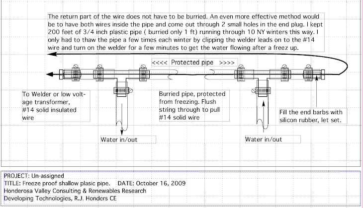
The most difficult part of a hydro project is building it to deal effectively with the extremes of nature. Of the various challenges nature provides the most difficult (in our situation and location) is extreme cold. When the temperature drops towards zero degrees F the water running over the rocks becomes super cooled ( below 32°F). It turns to slush and plugs up any trash rack in the way. Compare this summer low water scene looking down stream into the intake flume and trash rack to the high water and winter scenes.


The slush completely blocks the trash rack and any liquid water runs around the intake. This shot is looking up stream, note the big rock that guides the water directly into the flume. Since there is very little debris in the slushy water I removed both the primary and secondary self cleaning trash racks to keep things flowing. With no metal parts for ice to build up on and attach itself, I was able to keep it flowing down the 550' of 8 inch steel penstock, but only after adding some insulation to the penstock where it could not be buried. This year I added a small (1/2") buried plastic pipe that feeds 45°F water, in winter, from a spring a 1/2 mile away and 150 feet up. This warm water squirts out and upstream from the intake at 1.5 gal/min. We'll see if it helps keep things flowing. I need a dubious emoticon here. It sure can't hurt. I'll report back.


The insulation I used is only about a quarter inch of foam, ordinarily used to seal between a footing and the sill plate of a building. It comes in 50 ft X 8 inch rolls at building supply depots. To protect the foam I spiral wrapped it with high quality roofing underlayment, and coated that with rubberized roofing compound. To make the spiral wrapping process manageable I cut the 3 ft rolls in half. Start the wrapping at the bottom and overlap a couple of inches so it sheds water. Note the power and control conduits are strapped to the penstock with stainless straps and are included in the insulation.


This is a picture of the first year freeze-up being thawed out. The ice covered dam is visible in the distance. This freeze-up probably would not have happened if the water had continued to flow into the flume, but I suspect that the trash rack gradually reduced the water flow to a standstill causing everything to freeze.


Here is a picture looking down the 200 foot waterfall in winter. There is actually water flowing under there! Note the as yet un-insulated penstock upper left going slightly down hill.


This shot shows the (temporary/test) intake box that has baffles and screens to separate the water from gravel, leaves etc. The flume is not yet installed. The gravel dump valve oulet is directly under the '24'. The penstock is right under the '7' and there is an 8 inch butterfly valve stem visible just above the '2'. See the drawing posted for more detail. This intake structure, being successful, will be made more permanent with concrete before the wood disintegrates. I hope it will last a few more seasons as is.
Try this link to a live webcam monitoring the intake, http://powershack.shacknet.nu:1026/

Click on Guest visit. Will have night lighting soon.