BMH Power Plant Engineers Operating Manual
A micro hydro turbine driving an induction generator is like a finely tuned instrument. It runs most efficiently when water flow and head pressure resonate mechanically with the turbine geometry and the rotational speed. The rotational speed generates a precise pitch of 60 cycles per second which in turn is tuned to resonate (electrically) with the load and a bank of capacitors to keep currents oscillating through the copper windings of the generator and create magnetic fields in synchrony which in turn produce the current that we can use to light up our lives.
Since there are significant energy flows to be controlled and contained, it is important to understand how to control the energy smoothly, avoiding sudden surges or stepwise impacts in both the electrical as well as the hydraulic circuits. The operator, typically an engineer or highly trained technician, must understand, and be able to predict the result of turning On or Off any circuit breaker, switch or valve before actually touching a breaker, valve or controlling device. (In many localities grid-connected power plants are required to be operated under the supervision of an engineer.) Always check the readouts first to find out what loads are being powered when making any changes, and try to anticipate the result of the adjustment and the effects on the connected load. This manual will explain each switch, breaker, valve and controller and the function each serves.
This manual will give the procedures for startup of the plant, planned shutdown, unplanned shutdown and subsequent startup procedure. Monitoring and metering will also be explained. It may be useful for the more experienced operator to refer to the diagrams for further insight to the operation of this plant.
Conventions and Definitions as they apply to the Buttermilk Micro Hydro plant:
Storm Water Diversion: currently a pair of logs placed at an angle ~12 feet upstream from the water intake. Their function is to protect the down stream intake structures during extreme weather events. (Maintenance or future enhancement / automation project.)
Water flow measuring weir: located immediately upstream from the water intake. Functions to get an approximate measure of total water flow reaching the intake. (Maintenance or future enhancement / automation project.)
Slide gate: at the entry to the flume, function is to shut off water at the water intake during severe weather events or flume repairs.
Water intake: the 8” x 48” rectangular opening in the upstream end of the flume.
Warm water feed: the warm Honderosa spring water fed via (blue) underground pipe that keeps the water intake from freezing closed during most subzero winter nights.
Flume: the structure that currently carries the water from the water intake to the gravel baffle (and screening) box. (Maintenance or future enhancement /automation project.)
Minimum flow bypass: the circular opening in the flume bottom that insures the escape of a minimum of 200 Gallons / minute to keep the waterfall hydrated. (Maintenance or future enhancement / automation project.)
Gravel baffle box: the 4’ x 4’ x 5’ high (wood) box (Maintenance and / or future enhancement / automation project.) with the integral second gravel chamber and attached first gravel chamber, ball and chain flush valves, moving screen, screen drive mechanism, head valve, head valve drive / operator, and attached to the flume upstream.
Gravel Chambers: the first gravel chamber removes most negative buoyancy material that did not fall out of the minimum flow bypass. The second gravel chamber mostly collects fine sand and mud. (Maintenance or future enhancement / automation project.)
Moving screen: the HDPE conveyor belt screen that functions to keep floating or neutral debris from going down the penstock and clogging the turbines. The screen duty cycle can be adjusted so it does not clog itself with heavy debris loads or frazzle ice formation. (Maintenance and / or future enhancement /automation project.)
Frazzle ice: the slushy watery ice that forms in the shallower upstream rapids as water is super-cooled during sub zero nights. The frazzle ice solidifies immediately when it meets any cold or metal surface and blocks water flow. Once ice covers the stream no further frazzle ice will form and the water will run unimpeded underneath the ice cover, more so if snow also covers the ice. Even water falling vertically will be covered with ice.
Head valve: the butterfly valve and operator (motor and drive circuitry) at the bottom outlet of the gravel baffle box where the penstock connects.
Penstock: the 8” insulated or buried steel pipe that keeps the water contained
as the pressure increases going down to the powerhouse.
Green LED: indicates normal, OK, valve open, valve opening, green condition.
Red LED: indicates fault, valve closed, valve closing, red condition.
Orange Neon: indicates no power or reverse power flow from grid to generator. The Orange will extinguish when generator is operating normally and producing power.
NO: Normally Open contacts / circuit
NC: Normally Closed contacts / circuit
Manual Controlling Devices
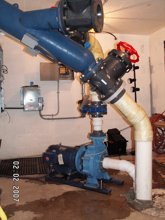
Valve1: The large PVC valve with red hand wheel that controls water flow to GEN1.
Valve2: The large PVC valve with red hand wheel that controls water flow to GEN2.
Valve3: The large PVC valve with red hand wheel in the middle that controls the dumping of water and debris into the discharge pit.
GEN1: Smaller 10kW turbine / generator
GEN2: Larger 15kW turbine / generator
Electro-mechanical Controlling Devices:
Rotork1: Valve and valve controller on GEN1 functions to automatically keep the speed of GEN1 constant when set to AUTO.
Rotork2: Valve and valve controller on GEN2 functions to automatically keep the speed of GEN2 constant when set to AUTO.
Electrical – Electronic controlling devices:
will add more, see comment balloons on Buttermilk manual 1.2.PDF
I. Start-up of water flow at intake
During warm weather months the flow of water to the turbine may be started (acquire ‘green’ condition) by following these steps.
The initial conditions are:
a. All power house valves closed, No water flow.
b. GEN(1 and 2) Rotork in manual / local mode and operated to CLOSED position.
c. Utility power present and fed through to homes, transfer switches in Normal mode, not Utility / Emergency.
1. Insure that there is at least enough flow in the stream to support turbine/GEN1 operation. This can be judged by observing the flow into the flume. Standing on the flume looking upstream, the water should cover ~80% of the width of the sloping bedrock stone weir, or within ~20% of the right side of the flume. (This measurement method should be refined when the temporary intake structures are made permanent by having a constant slope and marks ground or cemented into the trailing edge of the bedrock leading into the flume.)
2. Check that the moving screen (trash rack) is clear and operational. (see:Moving Screen Maintenance) Flush the 1st and 2nd sand and gravel settling chambers by pumping the ball valves (via stainless chains) up and down several times or until the water flows clean from the flush opening. (This procedure should be refined when the temporary intake structures are made permanent.)
The head valve can be operated from the powerhouse by a single push of the button on the Head Valve and Communications control box, observing the green LED for valve open and red LED for valve closed. An additional red/green LED lights only while the valve is moving to its newly commanded position, which takes ~100 seconds. Each push of the button reverses the operation of the head valve from open to close and vice versa with a 2 second delay.
Continuous operation of the trash rack can currently be implemented manually from a control box at the top of the falls in the old pump house. (Maintenance or future enhancement /automation project.)
II. Start-up of co-generation.
The initial conditions are: all the above and:
1. The ORU utility grid is assumed to be always present when starting up. If ORU fails while BMH is running, BMH continues independently, disconnected from the grid automatically via the Beckwith 3410 intertie protection device.
Open Head Valve (press button once on Head Valve and Communication box), wait for valve to open as indicated by ONE green LED. (the ‘green’ condition)
After 15 minutes check that pressure is stable at 95 PSI. (It was previously insured that a good volume of water is available in stream above and no ice/sand/gravel is present in penstock water.
(See: “Winter Icing Conditions” for cautions.)
2. Utility grid power ON. Beckwith 5 minute timer expired and ‘Output 1’ RED LED is ON and GREEN LED is blinking.
3. Top four load side breakers ON. We are using grid power as indicated on the Net Grid meter lower right in Beckwith enclosure.
4. Bottom six Generator side breakers OFF. We are not making any power yet.
5. Check for nominal meter readings of Honders ~1-3kW, Buyske ~ 1-3kW, NET from Grid −3kW to −8kW on PM620 meter in lower right hand corner of Beckwith enclosure. (The signs will change once the PM620ʼs are directionally adjusted to conform to Utility practice.)
6. REV PWR RESET to OFF (down) (located under Beckwith 3410)
7. Open the GEN 1 or 2 (which ever one is being started) manual main (RED WHEEL) valve to 50%. A red line on the valve stem indicates 50%.
8. Open GEN 1 or 2 Rotork in MANUAL mode to get RPM ~2000 using manual mode with the lever and hand-wheel or local control with open / close switch. Observe open / close LEDs in Rotork housing, after alternating red/green both should be OFF indicating speed is within range.
8. Switch REV PWR RESET to ON (up) (located under Beckwith 3410)
9. GEN1or 2 breaker ON, never both.
10. C1 breaker ON for GEN1. C1 and C2 breaker ON for GEN2. (Do not run both GENs simultaneously.)
11. Switch Rotork valve to REMOTE (automatic enabled). The Rotork controller should now open the valve slowly to maximum power.
12. Observe pressure gauge reading, (~90 PSI GEN 1, ~80PSI GEN 2), holding steady, not dropping for lack of water at the top or too much power input to GEN2. If too much power revert to manual control, 5/8 open 80 psi.
Check that the Reverse Power Relay ORANGE light is OFF.
Check PM620 Grid Power, Summary kW3Ø 5 to15 depending on house loading.
Check that power factor, PF3Ø > .90 or as close to 1.000 as you can get by switching breaker C2 and/or C3. Closer to 1.00 is better. If PF3Ø is - (negative) then turn off C3 if you can get closer to +or- 1.00
Check that the pressure remains stable at ~90 PSI GEN 1, ~80PSI GEN2.
If it is raining/snowing be sure to set the trash screen to continuous mode to prevent clogging.
13. GEN1or2 set the Rotork valve controller to REMOTE (automatic enabled).
14. Set (Honders and Buyske) house meters to read kW3Ø.
15. Switch REV PWR RESET to ON (down) (This may change with further automation.)
III. Shut-down of water flow.
During warm weather months the flow of water to the generator may be stopped (‘red’ condition) by closing either the head valve, the manual valves, or the Rotorks in the powerhouse and following this sequence:
The initial conditions are:
a. Head Valve open, normal water flow. ‘Green’ condition.
b. GEN(1 or 2) operating, Rotork in automatic control mode.
c. Utility power present and BMH power fed back to grid and through to homes, transfer switches in Normal mode, never Utility / Emergency. (This can be assured by opening the main breaker, interrupting the O&R ‘Emergency’ source from the ASCO transfer switch at the house.)
1. Set the GEN(1 or 2) Rotork to Manual.
2. Switch REV PWR RESET to OFF (up) (located under Beckwith 3410)
3. Set the Rotork to manual / local control mode.
4. While observing the Valve position indicator on the Rotork operate the valve to its fully closed position. All should be quiet now.
5. Turn off all (lower) Generator side breakers. Do not touch the upper 4 Load side breakers.
During cold weather months or anytime there is a danger that BMH may stop generating power it is best to switch REV PWR RESET to OFF (up) (this will change with further automation.)
During cold weather months the stream water flow must be kept from entering the penstock by:
1. Lowering the slide at the entry to the flume. (needs improvements with the rebuild)
2. Pull up 10” and hook both gravel flush ball valves.
3. Check that warm water flows down penstock to keep it from freezing solid.
4. Turn off all (lower) Generator side breakers. Do not touch the upper 4 Load side breakers.
Winter Icing Conditions — CAUTION
Over the years I have made continual improvements to the ‘temporary’ intake structures to mitigate some of the problems with slush and ice in winter, leaves in the fall, sand gravel, rocks, logs and debris washed down every time it rains more than an inch or two overnight.
Most winter problems would be greatly reduced or eliminated if there was a deeper reservoir to draw water below the surface ice layer, but not so low as to suck up sand and gravel. ( An 8” high x 48” wide opening just above the low, upstream, end of the moving screen could be opened to take water in through the screen if the water level is raised just above this opening.) The first fall excursions to single digit temperatures will probably not cause slushy (frizzle ice) water. But after a day or two of sub-zero nights frizzle ice will start to dam up flowing water especially any place where there is the slightest restriction or shallow water flow. So the first problem occurs under the storm water diversion logs which will definitely have to be repositioned or removed in winter. This means that they probably will not be able to be repositioned before the spring thaws to deflect the likely storm waters.
The second problem area is the 8”x48” primary intake at the upstream end of the flume. The water arrives super cooled to below freezing, carrying slush. Icicles form along the top edge of the 48” wide opening and grow rapidly together to the bottom of the flume and, with the slush, completely block the inlet in short order. Then the upstream water rises until it flows around the plugged up intake opening, dropping the head pressure, and starving the turbine.
Shutting down the power plant under these conditions is both difficult and risky. The valve stems and motor drivers tend to be frozen in place or are unable to close completely because of the cold and icing. This allows a trickle of water to continue down the pipe with increased likelihood of freezing inside the penstock. All means should be employed to keep a flow of water going down the penstock to keep that from freezing solid and potentially bursting or splitting or having it frozen until spring thaws. To facilitate this I have installed piping that carries warm water (45°F) from our hillside spring (and domestic water supply) to the intake structures. This warm water is normally directed to the intake opening to keep that from freezing but if a complete shutdown in winter is desired then the warm water is redirected to the penstock in the trash conveyor enclosure by a diversion valve (yet to be installed). Then to complete a safe shutdown both gravel dump ball valves must be lifted 10 inches and chained open. The slide gate at the upstream intake should be slid all the way down to minimize water entry. Now the only water going down the penstock should be the warm 45° water from the spring.
Exercise extreme caution when restarting the plant after a shutdown forced by extreme cold. It is possible for ice to come loose from the penstock walls and damage valves, pipes and turbines. If ice in the penstock is a possibility then the dump valve should be opened slightly to allow a low flow (~60GPM) through for 8 to 12 hours to insure all the ice is melted before starting the turbine /generator.
The most risky procedures in plant operation are shut down and startup. A running plant is far less prone to be damaged by nature or human error.
Gravel baffle box, aka Trash rack / conveyor.
The Gravel baffle box is still the (2007) original temporary wood construction and needs to be reconstructed of more durable materials. At the same time the badly worn down concrete and stone dam needs to be restored to its original height as planned in this earlier graphic:
The rebuilt trash conveyor box may be left in the current place and configuration with just an 8” x 48” opening added to the upstream side just above the lower end of the trash conveyor belt to allow water to enter. The trash conveyor has been very effective in minimizing fall leaf drop and debris problems. The higher water level behind the dam will minimize freezing problems in winter.
The Gravel Baffle Box: Raising the water level behind the low stone dam will minimize winter icing problems.
The debiting and crediting of kWh is done inside the ORU NET METER in real time as power flows back and forth as local demand and generation fluctuates.
Beckwith M3410 Grid Intertie Protection Relay
The Beckwith relay monitors the grid side of the system. If the grid goes out of normal bounds it will separate BMH from the grid. During normal BMH-grid-connected operation, if the grid goes out of bounds it will also pull BMH out of bounds with it.
(Approximate bounds are: 59.3 Hz to 60.5 Hz and 211.2v to 288V for a 240 V system)
When the programmed trip point is reached the Beckwith will separate BMH from the defunct grid and the BMH valve controller will attempt to match local generation to the new load conditions for OFF GRID operation, sparing the line men working on the dead grid, while continuing autonomous (also called 'islanded') operation.
The Reverse Rower Relay will monitor the direction of energy flow in the connection between the BMH generator and everything else. If the water flow decreases or stops and the generator output starts to drop below a programmable minimum, the Reverse Rower Relay will open the relay in the
generator connection, preventing grid power from flowing to the idled generator and causing it to 'motor'. Refer to the One Line Diagram to see more detail, or the Power House wiring diagram for even more detail.
All monitoring functions are provided via webserver at: http://Powershack.Shacknet.nu:1300
After entering a username and password all real time data as well as accumulated totals may be read remotely using a standard web browser. (Chrome / Mac seems to work the best.)
Grid Supply to BMH Generation
The Beckwith 3410 automatically switches from ORU to BMH and vice versa, depending on the adequacy of BMH generation to meet the demands of Honders and Buyske distribution.
Individual ORU Accounts and Automatic Transfer Switches
With all electrical service to homes drawn through BMH, the individual accounts with ORU, as well as the automatic transfer switches previously installed, are redundant and unnecessary.
ORU residential accounts may be discontinued. When BMH has disrupted operation, grid power is directed to each residence through the BMH account, using energy credit accrued.
Distributed Intelligent Load Controllers (DILCs)
DILCs installed on water heaters, clothes dryers or other high-demand appliances were intended to modify the jolt of instant demand on the BMH system by ramping-up the power from BMH to the appliance, thereby lessening brown-outs or other effects on the system. With the grid connection, the system reactive power is greater, and thus able to handle the fluctuating loads and obviating the need for the DILCs.
As long as the trash screen is in place and operational and gravel is flushed after every heavy rain fall, cleaning of turbines is unnecessary.
Generator Bearing Replacement
The job of generator bearing replacement maybe too cumbersome to be done in the powerhouse. At the point that bearings become worn and need replacement, the turbine and generator may be disconnected from the system and taken to a qualified pump repair service.