Monday, September 16, 2013

Some Energy Basics


Some answers, can you guess the questions? 

Yep, I am asked about pumping water back up the hill about once a week. And I'm not saying 'never works' , only that you'll never get more energy out than is put in. 

In some cases it pays! If electric costs at night are 1/3 of daytime charges you could make money by using twice as much electricity to pump the water up than you will get out on the trip down through the turbo generators during daytime with rates 3X higher.

A rough approximation for power (Watts) you can get from water at a height is: Gallons per minute times feet of height all divided by 14. So with the given 12 feet and 1000 gal/min you could generate about 900 watts for 15 minutes starting with the 15000 gallon tank full. To fill the tank would take a bit more than 900 Watts for a little more more than 15 minutes, and so you would end up with a net loss of energy every time around this loop. You would be better off with just a wind mill  and some solar panels, and using storage batteries instead of the water tank scheme for storage.  

One HP is 746 Watts, so a 100 HP motor would require 74,600 Watts for however long it runs with a load. And if you want to use the motor as generator you would have to have 74,600 Watts of water power where you only have 900 Watts for 15 minutes, or 450W for 30 minutes, or 0.225 kWatt hours from you water tank. So a half HP motor would be more appropriate as a generator.

Start with these basic numbers and estimates, then decide on the size of the equipment to handle the available energy. A 100HP motor does not make 100HP unless you put that much energy into it, either electrical or mechanical shaft rotation. It only converts mechanical to electrical and vise-versa. And if you use too big a motor (energy converter) for the energy input you will waste a lot of energy in bearing friction, windage and other losses. So it is important to match your machinery to the energy source. Don't buy machinery before you determine what the available energy sources can deliver. Measure head and flow, wind velocity over time, or sunshine over time, then calculate Watts or kiloWatts available and see if this will meet your needs at a reasonable cost. With wind and solar you can install a bigger mill or more panels to get more kWatts while the wind blows or the sun shines. With water there only flows so much for so long on average and a bigger turbo-generator may not be able to run efficiently or at all during low flow periods or dry spells.

Monday, July 29, 2013

The Ultimate Renewable Energy

Take away message from ICCF18, THE Cold Fusion Conference.

1. Anomalous heat, with power density far beyond what can be obtained from chemical (outer electrons, burning) reactions can be obtained routinely and repeatably.
2. If it is not chemical then the energy must come from the nucleus or its constituents as is borne out by the clear detection of transmutations, even if neutrons and other high energy particles are below easily detectable (and safe) levels.
3. AHE, LENR, CF or whatever the name, is a real and imminently more useful effect than fission because it can produce the energy of fission without the dangers or pollutants.
4. Efforts are underway, worldwide, to bring the technology to market, even absent a widely accepted theory of operation, as evidenced by successful demonstrations by several companies.
5. There is no doubt that as more testable theories are proposed the 'effect' will become better understood and be optimized for a multitude of applications including energy production.


Opening Session of ICCF18    7/21/2013

All the LENR luminaries are here including Peter Hagelstein and some that I had met up at MIT's 'Cold Fusion 101' in January '13.
Peter handed me a 'LENR intro short course' sponsored by National Security Innovation Center (NSIC) that he had prepared for the early Sunday morning session that I missed. I'll be reading that until my eyes close right after this report to my friends and family.
I've got to say that the 200 or so attendees were top notch and many known to me by name and some by sight from their research, web activities, postings and previous meetings. I have the complete list so I won't mention any more names now. 
A great many of the big names I spoke with had renewed confidence that Rossi's 'E-Cat' is for real after the independent testing and reporting that took place a couple of months ago. At the same time, none could confirm having achieved similar power gains (COP =6) with any consistency and duration. So my question, often repeated, was how long before someone else hits the magic formula / potion / catalyst or conditions that make LENR a viable power producing reaction? I have a few other questions that I hope to have answered this week at ICCF18. All in all a great start.
Will keep you posted.

Hi Condensed Matter Physics or Anomalous Heat Effects (AHE) or LENR or Cold Fusion etc. etc. followers,

No I'm not making light. This stuff is serious. Ten to twelve hours a day spent at Mizzou U and I've already got a serious headache trying to wrap my head around all I've learned. Talking ( which is not my strong suit) and listening to many scientists here, I've learned a lot about the discontinuities in the thinking about an appropriate theory that covers all the observed phenomenon. I watched the live feed from the Defkalion demonstration where the input was about 1900 Watts and the output was 5800 Watts! OK, maybe not as impressive as a gain of 6 or 60 that others have claimed but impressive to put on this kind of demonstration at this venue of 200 + knowledgable people in the field. Defkalion said they will make all the data publicly available. I have no doubt that if there is anything deceptive going on, this bunch will be all over it in a nano second. 
Another long, exciting day tomorrow. Will tour the Nano Tech facility at 4:15 tomorrow and the SKINR (LENR, AHE) labs at 11 on Thursday. Best of all are the in-depth one on one 'poster board' discussions where all related and even remotely related questions are discussed. 

More impressions from ICCF 18 in Columbia Mo. 7/2013 and some links.

A very impressive group of researchers, scientists and engineers meeting to advance the cleanest, safest form of energy ever discovered. Nearly as powerful as fission or fusion, these Anomalous Heat Effects, (AHE) discovered over 24 years ago by chemists Fleischmann and Pons, were largely ignored at the time because there appeared to be no immediate way to create military weaponry (explosions with fallout and deadly radiation) using the clean, 'atomic weak force'. Now, after nearly a quarter century, we are about to exploit AHE to solve the bigger problems threatening to destroy us all.

AHE also known as LENR (Low Energy Nuclear Reactions) and cold fusion still has a huge image problem with the general public which will need to be addressed. When we can buy a hot water heater that uses no fossil fuel and very little electricity (less than a 50 Watt light bulb on average) and with that (and a $50 nickel and hydrogen fuel cartridge) heat your whole house for a year and give you copious hot water as well, the image problem will disappear. 

The next hurtle for this to happen is regulatory (UL, CE) approvals and certifications. This being a brand new technology for home use, with a poorly chosen name and lots of vested fossil fueled interests... well, you can see that this will take a little longer even though similar devices already exist and are being tested with positive results.

Someone commented that the tools to be able to elucidate LENR phenomenon are just now being developed. I think this is only half the reason for the lethargy in LENR R and D.
It is not so much that research tools are lacking, it is more that the young scientists with the energy and zeal to apply them are absent. This became clear to me as I scanned the auditorium at ICCF18. My guess is that the average age of the 200+ attendees was somewhat past retirement age. Our educational system and the way we fund it may be the cause. Hopefully, renewed emphasis on Science, Technology, Engineering and Math (STEM) will help reverse this, but only if we are willing to fund education more equitably, not based on local wealth.
The Defkalion Reactor Cross  Section 195mm X 213mm, 6KW heat output


Thursday, February 7, 2013

OK, You've measured head and flow, what's next?


Assuming you have some good figures for head and flow your next step should be penstock sizing. Go bigger when in doubt. The pipe doesn't cost much more compared to the labor.  If you had 200' of head, that's great, how long a pipe will you need? Have you measured the flow through a couple of seasons? If you email me some pictures with someone standing in the stream I can give you a ball park flow figure.  
Also check with local water resources authorities for flow data. Or take some rough seasonal measurements as explained on my blog. You'll want to size your power plant so that you will have enough water to run 95% of the time. This is why sometimes it is better to have two turbines of different sizes so when you don't have enough water to run the bigger unit you can at least make some power with the reduced water flow in the smaller unit. The head is constant, but the flow is the variable to be able to adapt to. The best way to adapt using a PaT is to have two.
Pump/motor working asTurbine/generator units are cheap and it is nice to have two PaTs in the powerhouse, one for low flow and one for high flow. It also gives you a backup power source incase of breakdown, maintenance or repairs.

Concentrate, and don't skimp, on the  intake structure, penstock and powerhouse first. If you run out of money with those three items, just get a split case pump on Ebay save the $9K to 12K you'd be paying for an 'engineered system'.  For this site you would be looking for a 3X4X12 with a 20 to 40 HP, 3 phase motor. An 'end suction' centrifugal pump will also work but is somewhat less robust. 

Here is a source of used steel pipe on my Blog.

How far a distance is your planned home from the planned powerhouse? I'm asking because most 3 phase motors can be set up for 480V so you can transmit power over longer distances with thinner wire and then using a step-down transformer at the house will give you better regulation plus the standard 240V/120V service.

Friday, January 18, 2013

Turbine Speed, Torque, Flow, Pressure, and Efficiency Relationships

Here is some information you may find helpful in evaluating speed torque flow and power relationships in rotating machines. The graph showing these relationships works for most any rotating machine once you recognize that Volts, (the pressure pushing electrons) is analogous to water pressure, and current (Amps, the flow of electrons) is analogous to flow of water. And just like head Pressure x Flow= Watts so too Volts x Amps = Watts. Consistent units of measure have to be used to have this work out to the same numerical values.
In most well designed turbines, the runaway, or no load speed is ~1.8 to 2 x rated load speed. This means that under no load conditions the water slides by the impeller surface, without transferring any energy because they are moving at nearly the same speed. Another feature of the runaway speed is that the turbine output shaft torque is zero, (nothing loading it) no matter how much water flows through the machine.

The mechanical power is therefore null (about twice the rated speed multiplied by zero torque). The torque will rise by applying an external braking torque (the electric generator and its electrical load does that), while the speed will decrease, and that means you will start harvesting power (the water slips partially by the impeller, partially "pushing" it = energy transfer). You are moving (left on the speed axis) towards the best operating area where you will have rated torque, speed, and power.

Note that water consumption or flow also decreases so you are getting more power for less water and better efficiency. For simplicity the torque and flow plots are shown as straight lines whereas in most cases these curve, particularly near the ends.

Compared to this best operating point, if you apply even higher braking torque ( or electrical loading), the turbine speed will go down, while the torque will go up. You will ultimately reach the standstill point (turbine stalling), where the impeller is standing still, the water hits them with the greatest force (torque around 2 x T normal). Again, the power is null (zero speed multiplied by twice the rated torque). Basically, while you go from zero to runaway speed, the torque decreases with the speed, from 2x Tn at zero speed, to zero torque at 2 x rated speed. If you multiply this torque characteristics with the speed, you will have the power vs. speed curve, which is the yellow hill shaped graph, having it's maximum around midway between the speed extremes, 0 rpm and No Load rpm.

Note that for best efficiency, you will want to increase the turbine loading a bit, by reducing turbine speed (with a slightly larger pulley on the turbine, while maintaining synchronous speed on the generator). If you are just looking for maximum power (as when water pressure and volume are free and plentiful) run at a higher speed where the (yellow) power output peaks.

Here is a slightly different explanation (not mine) from the point of view of a pumping application:


Centrifugal pumps are bound by the Laws of Affinity. With respect to the speed of the pump, here are some facts. There is only one way to increase or decrease the head (pressure) that a centrifugal pump will produce. That is to vary the "tip speed" of the impeller. If, for instance you have an impeller with a 5" diameter, and it is spinning at 1750 RPM, the tip speed would be 20.825 fps. There are two ways to increase the tip speed you can 1) - Speed up the driver (say from 1750 RPM to 2000 RPM) 2) - increase the diameter of the impeller thus increasing the travel of the tip of the impeller in each revolution. Now the Laws of Affinity say that the Head changes in proportion to the square of the speed. That is how you can predict the head you can get from the impeller. These laws also say that the flow changes in direct proportion to the tip speed. As you can see, these predictions are based on the CHANGES in the tip speed. The flow, for instance, is relative to the height and type of the impeller. A wider, thicker if you will, impeller delivers more flow than a lower, more narrow impeller. So you see where i am going with this. The element that is missing is satisfied by - testing. You test the impeller and adjust as necessary with predictable calculations. 
"The Commoner"

Happy Hydro
Rob
Honderosa_Valley_Consulting@IEEE.org

Wednesday, December 5, 2012

Three Phase Motor as Single Phase Generator

To get single phase electricity from a three phase motor being spun as a generator you'll need to add some oil filled motor run type capacitors.
Here is a more fully developed diagram:

Monday, February 13, 2012

Connecting your generator to the grid

Power companies require that you disconnect your generator from the grid whenever grid power is lost or goes out of spec. (This is different from the function of a generator 'transfer' switch.)
The Beckwith M-3410 Intertie/Generator Protection Relay is 'approved' to perform this function.

This is basically a computer in a box that monitors voltage, frequency & currents and opens or closes contacts when anything goes outside of programmable limits. You will need an additional contactor (relay) to carry the main current between your generator and the grid. The 3410 will control the 'coil' of this relay.

The M-3410 can also display and track voltages, currents, kWhrs and much more information on a connected computer.

You will also need a little more circuitry for a system with added features, like possible off grid operation or high voltage transmission (480V) for longer distances to the power house.


Wednesday, January 4, 2012

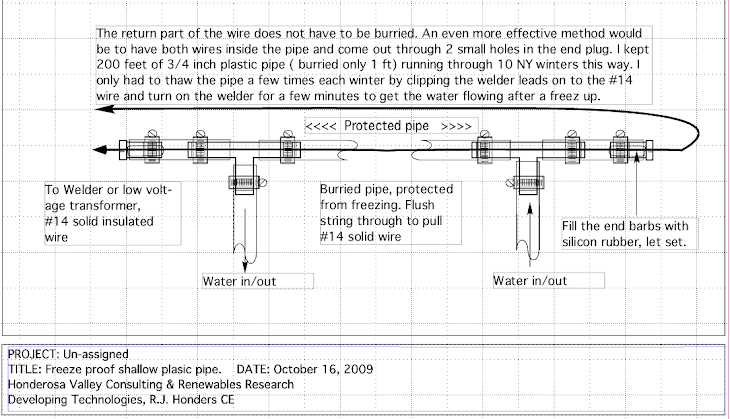
How to keep water pipes from freezing and free air conditioning.


I was wondering if you might have a suggestion on how to get an above ground water line from an Artisian well to NOT FREEZE.  This is the water source for the ducks and chickens, and am looking for a way to keep it from freezing over.

First, a couple of assumptions. I assume that the water pipe is made of black plastic, and is gravity fed from the artesian well that you mention. 
Depending on just how long the pipe is and where there is a 120VAC outlet to plug in a (400 to 600 Watt 12V) landscape lighting transformer in relation to one end of the pipe, the following will vary somewhat. The idea is to PUT THE HEAT INSIDE THE PIPE. You may also want to insulate the pipe.

You will need a length of 18 to 24 gauge twisted 2 wire, solid, insulated, 'bell' or 'thermostat' wire as long as your pipe plus 5 to 10 feet to reach the transformer and snake it through (inside) the whole length of the pipe. This is best done by first flushing a strong nylon pull string through the pipe with which you can pull the twisted wire pair through the pipe. At the well end have at least 6 inches of wire out the end and folded down over the edge and taped to the outside of the pipe to keep it from pulling back. Strip the wire ends here and twist the bare wire together securely and tape.
At the down hill end, (unless the pipe is just open ended and running all the time which might keep it from freezing all by it self ) drill a small  3/16" hole in the pipe, 3 inches back from the shutoff valve, and have the extra 5-10 feet of wire come out here. Seal around the hole and wire with silicone rubber and tape over the wire and hole to seal and provide strain relief for the delicate wire. It is best to have this valved end fastened to a 2X4 staked in the ground.

Next, connect the  2 wires to the 12V terminals on the landscape lighting transformer. If you just want to thaw out the pipe on occasion then you can just plug in for a few minutes to thaw it out, or maybe use a timer to turn the transformer off afterwards incase you forget. A safer method would be to use a ceiling fan control or lamp dimmer built into a standard electrical box/outlet plug the transformer into. Now you can adjust the power to the wire in the pipe to just keep it thawed and not use more electricity than you have to. I would also connect a 12V lamp at the transformer terminals (with the wires) so you have an indication of power flow to the wires (brighter bulb more heat to the wire/pipe).

Use heavier wire for longer runs, ie 18 Ga for 100', 24 Ga for <30'. If your pipe still freezes during very cold nights (T<20°F) you will have to insulate ( or bury) the pipe as well or use a larger transformer like 1000 Watts at 12V. You can get all this hardware at Lowes or Home Depot. Pictured below is a way to do a pressurized system.


I had to answer this suggestion if only to keep this guy out of trouble.

Radiators that can run COLD in hot weather, now THAT is an interesting and totally new idea you should patent it! 

PS sorry if that last remark seemed sarcastic, it wasn't meant to, I really mean I have never seen a system where the radiators produce 'cool'.


I have tried running cold water through existing radiators as well as radiant heat pipes embedded in my floor. The problem is the condensation from the sometimes very humid air in the summer here in NY. Puddles form under radiators and cool floors will become wet with condensation.
I solved those problems by running the cold spring water, gravity fed, through an 'A' coil like heat exchanger (radiator) with a condensation collection pan and drain. A small fan / blower blows the room air through the A coil thus cooling the room. Almost free air conditioning. 

Thursday, December 8, 2011

BOOST RENEWABLES - give us feed-in tariffs

There are a lot of interesting laws being considered to boost investment and viability of renewable energy sources. Net metering is just one, then there are feed-in tariffs and virtual net metering also called remote net metering or aggregate net metering.

In situations where multiple investors ( a group of neighbors ?) want to share the output of a renewable energy source, and perhaps these investors are remotely located from the source, virtual net metering will allow the renewable energy produced and metered at the source to be credited to any other investor meters out there on the grid.

Feed-in tariffs insure that renewable energy sources receive the same or higher price for their energy as fossil fueled (and subsidized) sources. Seems only fair, but currently in NY, the utilities are allowed to pay less for clean renewable energy, or only what is called the 'avoided cost', somewhere around 4 cents / KWhr  while charging a retail of 10 to 16 cents / KWhr.  A feed-in tariff would set ( and stabilize) the price somewhere in between so that investors can be certain of their return on investment and not have to gamble that the price of renewable energy is set by those that have a vested interest in burning fossil fuels.

These laws are slowly being passed piecemeal state by state. Eventually I look forward to progressive national legislation on this front. There is still lots of resistance from vested interests, but they are slowly figuring out that this kind of legislation does not hurt too many and helps boost renewable energy generation and national energy independence.

Wednesday, September 7, 2011

Survived Irene - barely

This video was taken after the water crested and pretty much covered the flume, causing it to rise up and down on the flood waters. Managed to save it by clearing debris from the inlet to flood it and weigh it down. It would have been destroyed if I had not been here. The upside to all this wet ... been running all year and they just passed net metering for under 25KW hydro in NY!

Sunday, July 3, 2011

Three Phase to Single using a 3Ø induction motor as generator


Common Micro Hydro Misconceptions

Hydro power - common misconceptions.

1. If there is a waterfall just let the falling water hit some paddles to which the generator is coupled and you are in business.
2. Rainwater running from the roof could be used to make electricity.
3. Hookup a turbine or Pelton wheel to your faucet, incoming waterline, or garden hose and you can keep the lights on for free. 
4. How about if I have a 2400 gallon tank 100 feet higher on a hill that fills up in 24 hours. How much electricity can I get? Answer: it will light up a night light continuously or brew coffee once in 24 hrs. (1800Watts for 10 min) 
Or 300Watt hrs  = .3Kwhrs about 2 cents worth.

Thursday, June 2, 2011

Connecting to the Utility Grid


Net Meter Micro Hydro – The Road to Energy Independence
By Robert Honders, Honderosa Valley Consulting

Net metering is the single most effective policy government can implement to promote renewable energy derived from all sources. Why exclude waterpower? If net metering were extended to all small scale (under 25KW) hydro sites, we would see renewed interest in the restoration of thousands of micro hydro sites that have been abandoned during the times of cheap oil. Many of these sites could be made productive again with lower investments because the infrastructure (dam, penstock, water supply) may still be intact. There is no valid reason to treat one renewable energy source any differently than another. We need them all to pave the road to energy independence.
The advantages of a grid connection include energy storage and vastly simplified control of frequency & voltage. Essentially the site runs wide open and just pushes energy into the grid at the grid voltage and frequency. It is analogous to you helping a freight train by pushing on the back of it. You won't be able to change its speed at all, even if your efforts are doubled, or stopped altogether. In other words, your energy input can fluctuate, but the train stabilizes everything just as the grid stabilizes relatively small energy inputs.

The simplest way to get grid-connected and reap these stabilizing benefits is through net metering. Net metering is accomplished using a single-bidirectional meter, which is already in place on all grid-connected homes. But beware! The newer electronic meters are programmed by the utility company to ignore the direction of the energy flow. Thus you can end up paying for the energy that you send to the grid! The power company prevents small energy producers from sharing the energy they generate with their neighbors and turning their own meter backward without permission.         (Older spinning disk meters were not programmable in this way. The worst they could do to you is stand still while you were supplying power, and spin forward as you used power.)

To get grid connected with your hydro powered induction generator (cheapest, robust and most common) you’ll need to use an ‘inter-tie protection relay’ like the Beckwith M-3410. The relay monitors the grid / utility (not your generator) for any type of anomaly, like ‘grid down’, voltage or frequency too low / high etc. If any grid anomaly occurs the relay disconnects your micro hydro output from the grid for their protection. After grid power is restored the relay monitors the grid and if the grid has been normal for 5 minutes it will re-connect your micro hydro. You will need to wire an auxiliary contactor to hang a dump load (space heater will do) on your induction generator while it is disconnected from the grid to prevent your output voltage from rising too high.  Below you’ll find the diagram for a system like this. Double click to enlarge.

Once your utility has inspected and tested your grid inter-tie for proper operation, AND if your state law has hydro power included in the net metering law, then you can ask your utility company to re-program your meter so you can share your excess power with your neighbors and run your meter backwards. Net metering makes it possible to ‘store’ your excess energy in the grid instead of in batteries, and returns energy to you when you need it, perhaps during a dry August, and at the same price.                          

So let’s have NET METERING FOR ALL RENEWABLE ENERGY be the law of the land!


Friday, March 25, 2011

Pumps as Turbines have many advantages.


If you are good with welding you may want to consider making your own 'turbine' case to replace the pump case and use only the impeller, shaft, seals and bearings from a split case pump. This will allow you to design the turbine case with a much larger inlet to eliminate the restrictive pump outlet.  Note that pump outlet = turbine inlet. This will get you a little more efficiency in converting the energy in the water ( head X flow ) to mechanical shaft energy.


You could even buy just the parts you need. Example shown here. This is a project I'm considering, at least on paper. Another approach might be to modify a split case pump housing with a second outlet. (inlet with respect to turbine operation) Since these housings are mostly made of cast steel it would involve welding of cast steel or cast iron. I'm not sure it would be worth it for maybe a 5% boost in efficiency. But if you like to tweak and optimize ...

Thursday, February 3, 2011

Saturday, January 29, 2011

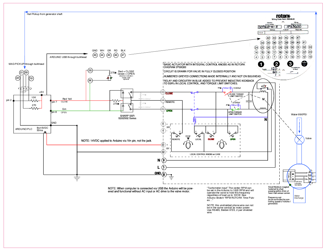
Arduino and bidirectional AC valve motor controller for Micro Hydro

The diagram, Arduino on left Rotork valve operator right, blue outline of turbo-gen extreme right.


       /*
      Generator RPM control Robert J Honders Sr 7/9/2013
      Changed: 8/30/13 to control the 120VAC motor on ROTORK valve actuator.
      Tuned: 2/7/2014, onsite w Gen1 on grid 
      and simulated unloading by switching off C1 then Gen1. 
      Loads continuously powered by grid. Still problem osc when no load.
      2/12/2014 tweaked program, added Inverse of Deviation element to help stay put within range.
      3/23/2014 Added intermediate Proportional error bands. 
      Rev6 3/24/2014 Reversed valve adjustment order to close first.
      Rev 6.5 added DeltaRPM to correct rapid changes. Abandoned that idea.
      Rev 6.6 Added more speed error bands, now 7.
      WAY OVER,  OVER,  NEAR+,  WITHIN SPAN,  NEAR-,  UNDER,  WAY UNDER.
      
      NOTE: A lot of testing stuff is commented out of the program. By removing
      the '//' you can get stuff to print out on screen. Input to pin 2
      can be simulated with 'hall effect' type pickup (TLE4906) and a tiny magnet
      on the VARIAC controlled test motor shaft. Here is a simple Arduino pulse generator 
      routine to give a 1ms negative pulse every 32ms (variable with a pot) for off site testing.


  I needed to have a variable source of negative going pulses, potentiometer adjustable, around 33 ms apart, 
  to simulate what comes from my Micro Hydro generator hall pickup. Just so I would not have to be in the
  noisy powerhouse to develop the PID valve controller to operate the motorized valves.(Another project.)  
  
  Control the frequency of pulse at pin 13 with 10K potentiometer, center to pin A0, one end to +5, other to GND.
  Not possble to use - delayMicroseconds() - if the pulses need to be shorter and faster because DelayMicroseconds
  is only good up to 16383. I got around that by dividing the time in four. Lots of details to help you
  and me understand it.   Robert Honders Sr 3/28/2014

//START OF TEST PULSE GENERATOR.

            // constants won't change. Used here to set pin numbers. 
            const int pulsePin = 13; // sets which output pin to pulse.  
            //Declare some variables.
            int OldPotValue;//declared here it is good throughout and only zeroed here.
            int PotValue;    //declared here it is good throughout and only zeroed here.
            int error;  //Really the change in PotValue as we turn the shaft.
            int minPotDelta=100;// This is the minimum change sensed in 100000, turning the pot.
                                  // this is to eliminate jitter in sucessive A/D conversion readings
            
  void setup()   // the setup routine runs once when reset is pressed.
          
          {
             Serial.begin(9600);       
             Serial.println(" pot variable generator RPM pulse simulator");
             pinMode (pulsePin, OUTPUT);// set digital pin to OUTPUT, they default to inputs.
          }
  
  void loop()  // the loop routine runs over and over again forever 
  
    {
             
      
            //Serial.println (OldPotValue); //milliseconds between pulses NOT?
           // delay (1000);
            
            PotValue = analogRead(A0);// read the pot input on analog pin A0:
            PotValue = map(PotValue,0,1000, 0,100000);//the second 2 can be swapped to get the pot to give higher RPM on clockwise.
            PotValue = PotValue/4;// divided in four to get around delayMicroseconds limitation, the latest pot value.
             
            error = OldPotValue - PotValue; // is it different than the last pot value by an amount called error
              
              
              if  (abs(error) <= minPotDelta) //error is change in pot setting if small change use OldPotValue, eliminates small A/D conv errors.
              {
                 
                PotValue = OldPotValue;// if the pot value changed by less than the minPotDelta than we will use the OldPotValue.
                   // if the pot is not moved we'll be up here.
                   digitalWrite(pulsePin, LOW);
                   delayMicroseconds(500);//fixed pulse width of half a millisec.
                   digitalWrite(pulsePin, HIGH);
                   
                   delayMicroseconds(PotValue);   
                   delayMicroseconds(PotValue);// four times to make up for /4
                   delayMicroseconds(PotValue);
                   delayMicroseconds(PotValue);
                 
                    //Serial.println ("no change ") ;
                    //Serial.println (PotValue);
                    //Serial.println (error);
              }   
                 
                 if  (abs(error) >= minPotDelta)

              {     
                   // if the pot IS adjusted we'll be down here.
                   digitalWrite(pulsePin, LOW);
                   delayMicroseconds(500);//fixed pulse width of half a millisec.
                   digitalWrite(pulsePin, HIGH);
                   
                   delayMicroseconds(PotValue);   
                   delayMicroseconds(PotValue);// four times to make up for /4
                   delayMicroseconds(PotValue);
                   delayMicroseconds(PotValue);
                 
                    Serial.println ("                  new PV ") ;
                    Serial.println (PotValue);
                    Serial.println (" Change in PotValue ") ;
                    Serial.println (error); 
              }
                  
                   OldPotValue=PotValue;//store the current pot value to compare with the new.
      }
          
      //END OF TEST PULSE GENERATOR.    


      The sketch uses a timer to work out the interval
      between two consecutive rising edges on pin D2. This time we use a "rising"
      interrupt on D2 to notice the leading edge. We also set up a high-precision
      timer (Timer 1) which is a 16-bit timer.
      
      By using no prescaler, Timer 1 counts 1 for every clock cycle (say, every
      62.5 nS at 16 MHz).
      By multiplying the number of counts between the leading edges by 62.5, and 
      then taking the inverse, we can deduce the frequency.
      
      The advantage of this method is that we get a very quick calculation.
      For example, at 10 KHz the period is 1/10000, namely 100 µS, so we get our
      result 100 µS later.
      
      Note that due to the time taken to service the interrupts on the data's leading
      edges, the maximum achievable frequency you can sample is around 100 KHz 
      (which would mean the ISR(Interrupt Service Routine) is taking around 10 µS).
      
       Frequency timer
       Author: Nick Gammon
       Date: 10th February 2012
       Adapted and annotated for Generator RPM control Robert J Honders Sr 7/9/2013 - 9/2/13
       
       
       A variable should be declared volatile whenever its value
       can be changed by something beyond the control of the code section in which it appears,
       such as a concurrently executing thread. In the Arduino, the only place that this is
       likely to occur is in sections of code associated with interrupts, called an interrupt service routine.
      */
      
      
      volatile boolean first;
      volatile boolean triggered;
      volatile unsigned long overflowCount;
      volatile unsigned long startTime;
      volatile unsigned long finishTime;

      // here on rising edge on pin 2, is interrupt 0 always on pin 2 ??
 void isr () //Start of Interrupt Service Routine
          {
            //digitalWrite(2, HIGH);//sets pin 2 hi eliminates 10 k pullup, can be left in crkt.
            unsigned int counter = TCNT1;  // quickly save counter 1 count in counter.
            
          
            if (triggered)// wait until we notice last rising edge
              return;
          
                  if (first)
                    {
                    startTime = (overflowCount << 16) + counter;
                    first = false;
                    return;  
                    }
              
            finishTime = (overflowCount << 16) + counter;
            triggered = true;
            detachInterrupt(0);   
          }  // end of interrupt service routine


  // timer overflows (every 65536 counts)
  ISR (TIMER1_OVF_vect) 
        {
          overflowCount++;//increment overflow count by 1
        }   // end of TIMER1_OVF_vect


 void prepareForInterrupts ()
        {
        // get ready for next time
        EIFR = _BV (INTF0);  // clear flag for interrupt 0
        first = true;
        triggered = false;  // re-arm for next time
        attachInterrupt(0, isr, RISING); //look for next rising edge and run ISR    
        }  // end of prepareForInterrupts

 void setup () 
      {
        Serial.begin(9600);       
        //Serial.println("Tachometer");
        
        // reset Timer 1
        TCCR1A = 0;
        TCCR1B = 0;
        // Timer 1 - interrupt on overflow
        TIMSK1 = _BV (TOIE1);   // enable Timer1 Interrupt
        // zero it
        TCNT1 = 0;     
        // start Timer 1
        TCCR1B =  _BV (CS20);  //  no prescaling
      
      
        prepareForInterrupts (); // set up for interrupts to get new RPM data.
        
      } // end of setup

int previousMillis = 0;        // will store last TIME RPM was updated.
int previousRPM =0;        // will store last RPM read.


 void loop () // the main loop will have to be modified for PID.
        {
      
        if (!triggered)// if NOT triggered 
          return;//wait here until it is.
       
        unsigned long elapsedTime = finishTime - startTime;
        int RPM = 60.0 / ((float (elapsedTime) * 62.5e-9));  // each tick is 62.5 nS
        
       
        /* 1800 RPM = .333s per rev = frequency of 30 per second X 60 s/min = 1800 RPM
           So 1800 RPM is 33.33ms / .0000625ms = 533,333 ticks or counts of the 16 Mhz Arduino clock in one revolution! 
           That hapens between pulses from magnetic "Hall" motor pickup, so we get very high resolution RPM, 
           any small change will be detectable, probably overkill.
        */
        Serial.println () ;
        Serial.print (RPM); 
        Serial.println (" RPM ");
     
        
        //Figure Delta RPM here and work it into the if over/under corrections.      
        int currentRPM = RPM; //store the RPM now
        int DeltaRPM = currentRPM - previousRPM; //the change in RPM readings.
        previousRPM = currentRPM; // save the last time you got the RPMs
        
       
        /*
        
        The following attempt at PID control not successful so far.
        // figure Delta T here
        int currentMillis = millis(); //store the count now
        int DeltaT = (currentMillis - previousMillis)/60000; //the time between RPM readings in minutes.
        previousMillis = currentMillis; // save the last time you got the RPMs
        Serial.print (DeltaT);
        Serial.println (" Delta T ");
                             
        int Deriv=DeltaRPM/DeltaT; // Drpm/Dt 1st derivative variable Delta T
        Serial.print (Deriv);
        Serial.println (" Derivative ");
        */ 


        //this section will run the valve motor for a duration proportional to the deviation or error
        // to close valve if RPM is HI, or to open valve if RPM is LO. Also DeltaRPM will reduce the effective RunTime.
        
        //Added setup code, Do these go here as part of setup??
        //Yes, did not work in "void setup()" above, local variable scope? do we need a second Void Setup.
        //******************SET*UP***********************
        
        int CenterRPM=1820;// 1820, adjust center RPM to open valve with minimum pulse width (green blink)in grid mode.
        int Span = 20;// 10, sets max + AND - deviation from CenterRPM, (+ plus - ), sets system accuracy.
        int WindDownTime = 1000; // 100-2000, time for motor to stop, ms, before next pulse, if within range it is multiplied by InvDevMag.
        int RunTime = 6;//2-10, motor run time to move valve, ms, automatically reduced if deviation is small, increased if deviation is big.
        
        //**************END*SET*UP************************
        float Deviation;// Error signal signed, + is fast
        int DevMag; //absolute value of Deviation, magnitude only, unsigned.
        float InvDevMag;//the inverse of deviation magnitude.
        int openPin = 8; // sets which output pin to open valve, these 2 pins must not both be high.
        int closePin = 7; //sets what pin to set high to close valve.
        pinMode (openPin, OUTPUT);// set digital pins to OUTPUT, they default to inputs.
        pinMode (closePin, OUTPUT);//analog pins do not have to be declared inputs or outputs.
        //end of added setup code 
        
        //DeltaRPM = constrain (DeltaRPM,-RunTime+25,RunTime-25); 
        //Serial.print (DeltaRPM);
        //Serial.println (" Delta RPM ");
        
        Deviation = RPM-CenterRPM;// positive is running FAST
                                  //if(Deviation < 0)//running slow, ERROR signal.
        
        
        if (Deviation == 0) (Deviation = 1);// so we don't end up dividing by 0 in the next line.
        
        InvDevMag =((Span)/Deviation);//less deviation bigger number, stay put longer time when within Span.
        InvDevMag =(abs(InvDevMag)); //no negative time allowed, Inverse Deviation Magnetude, small deviation stay put longer.
        //InvDevMag = map(InvDevMag,0,Span, 0,(3*Span));    
            
            //Serial.print ("Deviation ");
            //Serial.println (Deviation); 
            //Serial.print ("inverse of deviation ");
            //Serial.println (InvDevMag); 
        
        
        DevMag = (abs(Deviation));//just the magnitude to set the output motor RunTime time proportionally.
      
        
            //Serial.print ("DevMag ");                          
            //Serial.println (DevMag);
        
        //DevMag = map(DevMag,0,Span, 1,(Deviation)*Span);  // re maps 0 to Span >> 1 to abs Deviation*Span eliminates 0 from DevMag. 
        //DevMag = abs(DevMag);//no negative values   
            
            //Serial.print ("DevMag "); 
            //Serial.println (DevMag);
            
        DevMag = constrain (DevMag,1,2000); //keeps deviations from blowing up when motor stopped.
            //Serial.print ("Constrained DevMag ");                          
            //Serial.println (DevMag); 
        
        // These error bands progressively increase duration of RunTime and decrease duration of 
        // WindDownTime in proportion to the Deviation Magnitude or error, modulating the AC motor speed and direction.
       
        // WAY OVER,  OVER,  NEAR+,  WITHIN SPAN,  NEAR-,  UNDER,  WAY UNDER.
        
        
        if (Deviation > 2*Span)  // RPM Deviation way too high, close valve longer. 
       
                  {
                    Serial.println ("WAY OVER");
                    
                    digitalWrite(openPin,LOW);//GREEN LED off, allow CLOSE VALVE 
                    //delay(WindDownTime);//so we allow the motor to spin to a stop between pulses.
                    digitalWrite(closePin,HIGH);//RED LED on to CLOSE VALVE.
                    
                       delay (RunTime*DevMag/4);// keep motor running CLOSING valve longer if Dev Magnitude is big.
                    
                    digitalWrite(closePin,0);//reset RED closePin (5) to stop motor.
                    digitalWrite(openPin,0);//reset GREEN openPin (6) to stop motor. 
                    delay(2*WindDownTime*InvDevMag);//so we allow the motor to spin to a stop between pulses for shorter time if deviation is big.
                   
                  }


        else if (Deviation > (Span) && (Deviation <= 2*Span)) // positive deviations, RPM a little too high, CLOSE valve short time.
          
                  { 
                    Serial.println ("OVER");
                    
                    digitalWrite(openPin,LOW);//GREEN LED off, allow CLOSE VALVE 
                    //delay(WindDownTime);//so we allow the motor to spin to a stop between pulses.
                    digitalWrite(closePin,HIGH);//RED LED on to CLOSE VALVE.
                   
                       delay ((RunTime)*(DevMag/5));// keep motor running CLOSING valve longer if Dev Magnitude is big.
                    
                    digitalWrite(closePin,0);//reset RED closePin (5) to stop motor.
                    digitalWrite(openPin,0);//reset GREEN openPin (6) to stop motor. 
                    delay(4*WindDownTime*InvDevMag);//so we allow the motor to spin to a stop between pulses for short time if deviation is big.
                  }


        else if (Deviation > Span/2 && Deviation <= Span) // positive deviations, RPM a little too high, CLOSE valve short time.
          
                  { 
                    Serial.println ("NEAR+");
                    
                    digitalWrite(openPin,LOW);//GREEN LED off, allow CLOSE VALVE 
                    //delay(WindDownTime);//so we allow the motor to spin to a stop between pulses.
                    digitalWrite(closePin,HIGH);//RED LED on to CLOSE VALVE.
                    
                       delay (RunTime*(DevMag/2));// keep motor running CLOSING valve longer if Dev Magnitude is big.
                    
                    digitalWrite(closePin,0);//reset RED closePin (5) to stop motor.
                    digitalWrite(openPin,0);//reset GREEN openPin (6) to stop motor. 
                    delay(2*WindDownTime*InvDevMag);//so we allow the motor to spin to a stop between pulses for short time if deviation is big.
                  }


        else if (Deviation >= (Span/-2) && (Deviation <= Span/2)) //within span, just keep the Valve motor stopped longer.
                                      
                  {
                      Serial.println ("Within Span");
                        
                      digitalWrite(closePin,LOW);//reset RED closePin to keep motor stopped.
                      digitalWrite(openPin,LOW);//reset GREEN openPin to keep motor stopped. 
                      delay((InvDevMag/4)*WindDownTime);//Speed is within span so wait a while proportional to how close to center RPM 
                                                      //so we allow the motor to spin to a stop between adjustments.  
                  }
          
         
        else if (Deviation < (Span/-2) && (Deviation >= -1*Span)) // small negative deviations, RPM a little too low, OPEN valve short time.
          
                  { 
                    Serial.println ("NEAR-");
                    
                    digitalWrite(closePin,LOW);//RED LED off, allow OPEN VALVE 
                    //delay(WindDownTime);//put some time between OPEN and last CLOSE commands so we don't do both.
                    digitalWrite(openPin,HIGH);//GREEN LED on OPEN VALVE.
                    
                       delay ((RunTime*DevMag/2));// keep motor running OPENING valve longer if Deviation Magnitude is big.  
                    
                    digitalWrite(closePin,LOW);//reset RED closePin to stop motor.
                    digitalWrite(openPin,LOW);//reset GREEN openPin to stop motor. 
                    delay(2*WindDownTime*InvDevMag);//so we allow the motor rest a shorter time if dev is big, between pulses. 
                  }


          else if (Deviation < (-1*Span) && (Deviation >= -2*Span)) // small negative deviations, RPM a little too low, OPEN valve short time.
          
                  { 
                    Serial.println ("UNDER");
                    
                    digitalWrite(closePin,LOW);//RED LED off, allow OPEN VALVE 
                    //delay(WindDownTime);//put some time between OPEN and last CLOSE commands so we don't do both.
                    digitalWrite(openPin,HIGH);//GREEN LED on OPEN VALVE.
                    
                       delay ((RunTime)*(DevMag/5));// keep motor running OPENING valve longer if Deviation Magnitude is big.  
                    
                    digitalWrite(closePin,LOW);//reset RED closePin to stop motor.
                    digitalWrite(openPin,LOW);//reset GREEN openPin to stop motor. 
                    delay(4*WindDownTime*InvDevMag);//so we allow the motor rest a shorter time if dev is big, between pulses. 
                  }


         else  // big negative deviations, RPM way too low, open valve longer time.
        
                  { 
                    Serial.println ("WAY UNDER");
                    
                    digitalWrite(closePin,LOW);//RED LED off, allow OPEN VALVE 
                    //delay(WindDownTime);//put some time between OPEN and last CLOSE commands so we don't do both.
                    digitalWrite(openPin,HIGH);//GREEN LED on OPEN VALVE.
                    
                       delay (RunTime*DevMag/4);// keep motor running OPENING valve longer if Deviation Magnitude is big.  
                    
                    digitalWrite(closePin,LOW);//reset RED closePin to stop motor.
                    digitalWrite(openPin,LOW);//reset GREEN openPin to stop motor. 
                    delay(2*WindDownTime*InvDevMag);//so we allow the motor rest a shorter time if dev is big, between pulses. 
                  }


        prepareForInterrupts ();  // get a new reading of RPM   
      }   // end of loop